The Noise About Ultrasonic Inspection
-By Nick Allo, Superior Signal Company LLC
 For years ultrasonic inspection techniques have been used in plant maintenance programs to reduce energy costs, and increase equipment reliability.
In our daily interaction with those responsible for maximizing plant efficiency, experience shows that many who are using ultrasonics don’t really understand the physical principles behind the operation of these instruments. This can result in a false sense of security, and unrealistic expectations. This article will describe the physical basis of ultrasonic inspection, applications, and comparison to vibration analysis. Hopefully it will help eliminate some of the common misconceptions of ultrasonic technology.
The Basic Physics…
Ultrasonics, as the name implies, is sound above the human hearing range. The sound that you consider "noise" in your plant covers a wide range of sound frequencies. The audible sound that you hear is only a small part of the total spectrum of sound that actually exists. With the use of an ultrasonic detector, high frequency ultrasound is translated into the audible range where it can be heard through a headset. By listening to this high frequency sound and recording the intensity, plant maintenance crews can identify and diagnose a variety of potential maintenance nightmares.
Fric tion in moving equipment and turbulence in the flow of fluids and gasses emit high levels of ultrasound. In an industrial facility, pressurized leaks in pneumatic air lines, steam lines, and vacuum leaks emit ultrasound. Internal leaks in valves, steam traps, and hydraulic systems also produce ultrasound, as well as mechanical wear in bearings and gears.
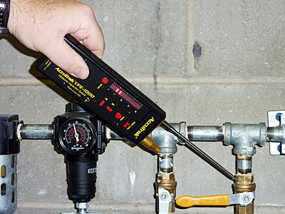
Leak Detection: Most are familiar with the importance of locating and repairing air leaks and the incredible costs that can be associated with such waste. Ultrasonics is the most effective way to locate these losses because it takes you into a different world of hearing.
Misconception - You can use an ultrasonic leak detector to quantify leak rates.
It is astounding that some ultrasonic user’s feel they can point their ultrasonic detector at a leak 20 ft away, read the meter intensity, and make a correlation between sound and cfm loss, therefore assigning a monetary value to the leak. Although you may be able to make some rough estimates, it is extremely difficult, if not impossible to make an accurate correlation between the size of a leak and the amount of sound produced by it. Think about what happens when you whistle. Changing the shape of your lips and tongue, and blowing differently will create different sounds. Compare this to a compressed air leak in your plant. A wide variety of sounds, and sound frequencies can be created by cracks and holes of different sizes, shapes and pressures. A large leak (.10 in) and a smaller leak (.004 in), side by side, under the same pressure, will create two entirely different tones.
It may not be uncommon for a smaller leak to actually produce more sound than a larger one. This is because the sound produced at the orifice is created by turbulent gas flow, and a phenomenon called edge effect. This is easily demonstrated if you can imagine a whistle’s edge which “cuts” the airflow starting the turbulent flow. This creates the sound that you hear.
Ultrasonics will detect any type of gas leak or vacuum leak provided there is sufficient turbulence. It is an excellent instrument for locating costly leaks, but not for quantifying their actual losses.
Ultrasonic Background noise
While the background noise in your plant may seem overwhelming, in many cases the sound present in the ultrasonic range (Area B) is not significant, and does not hinder leak detection. But what about when there is a high level of ultrasonic background noise? This is the greatest obstacle to ultrasonic leak detection. Locating the desired sound signature buried among so many others can be like trying to find a needle in a needle stack.
Misconception - Manual frequency tuning is the best way to reduce background noise.
There are two popular techniques used in ultrasonic detectors to avoid background interference…
Manual Frequency Tuning: This technique has been used for decades, and has its advantages for applications such as bearing tests (to be later discussed). For leak detection however, it can be frustrating in areas with extensive ultrasonic background noise. The idea behind manual tuning is that you can tune the instrument to a more narrow band, much like a radio, and capture the desired sound of the leak while decreasing the instrument’s sensitivity to background noise. When using this method you are basically moving a vertical window across the spectrum of sound. This is illustrated in figure 2. The technique is to move this window over the leak frequency, and away from the dominant frequencies of the background noise competition.
This technique is somewhat effective, however frustration can arise. As mentioned earlier, leaks come in all sizes, shapes and pressures; thus a range of dominant sound frequencies should be expected. You may not be tuned to the correct frequency at the appropriate time, meaning leaks are being tuned out as an effort is being made to find them!
Automatic Frequency Tuning: This technique has made ultrasonic detectors easier to use for leak detection as no frequency searches are required. Using a process named “Dynamic Noise Discrimination” (DND)*, these instruments decompose all of the incoming sound and automatically lock on to the unique characteristics of the leak sound. The technology does this by setting certain frequency and intensity criteria that a particular sound must possess to be translated to the user’s headset. Automatic tuning searches the sound spectrum horizontally, as shown in figure 3.
In very loud areas physical shielding is often necessary with both techniques. Moving the sensor as close as possible to the leak source, and shielding it helps with sound detection. Most ultrasonic detectors come with attachments which do this quite well.
 Bearing Analysis, Why use ultrasonics?
Bearings simply wear, as the rollers and races begin to loose their polish, imperfections appear on their surfaces. As these imperfections pass each other they produce high frequency oscillations, too high and subtle to vibrate the mounts or related machine members. Traditional vibration analysis and trending techniques using accelerometers cannot respond to these frequencies because they are many orders of magnitude above their range.
It is important to remember these basic definitions… SOUND is a microscopic vibration at the molecular level. VIBRATION is macroscopic mechanical oscillations that result in the motion of machine members. Sound is the precursor to vibration. It is vibration that is too fast and with an amplitude too small to move “large” masses.
Misconception - Ultrasonics is a less effective, alternate technique to vibration analysis.
For some less critical applications, ultrasonics may be used as an alternative, but generally it can be used synergistically when incorporated into existing vibration programs.
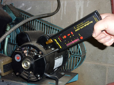
The early warning offered by ultrasonic detection can be used as a stand alone technique, or to compliment existing vibration programs. Using an ultrasonic contact sensor, simple bearing wear detection can be performed just by listening to the bearing in question. Judgements as to condition can be made comparatively from one similar bearing to the next. The technology is also excellent for slow speed applications. Scraping, grinding, and squealing can be heard by the user, but not easily detected using vibration analysis.
For higher speeds, most ultrasonic detectors offer some type of meter to record sound intensities. New digital detectors offer alphanumeric displays with peak hold making it easier to create a basic trend. Figure 4 shows inconsistencies in ultrasonic intensity readings which become clear by using an ultrasonic detector. This should serve as a warning that something is taking a turn for the worst. Ultrasonics is generally easier to use than vibration analyzers, and can be utilized by most anyone, including those less technically oriented. Information seen in the high frequency range of ultrasonics can be a signal to start looking at the lower frequencies. It is an initial test which alerts the technician of a problem later to be analyzed with vibration.
Ultrasonics can be used on more equipment in less time, allowing preventive maintenance to be done on less critical equipment which otherwise would have gone untested. With experience, you will become more confident judging condition and wear patterns using ultrasonics.
The manual frequency tuning techique is better suited for bearing tests. As a bearing wears, dominant frequencies shift. Using manual tuning ensures the instrument will consistently react to the same “window” of sound.
For more advanced analysis, ultrasonic detectors can be used in conjunction with a spectrum analyzer. Mathematical tools used in vibration analysis like the FFT, Power Spectral Density (PSD), Autocorrelation, Cross-correlation, Cepstrum and wavelet transforms, can be used to discover faults with any type of equipment. Generally, analyzers that can operate at high frequencies are expensive and not readily available, therefore it is easier to down-shift these frequencies to where the information can be processed. When doing this with a vibration analyzer, knowing the offset frequency will allow you to figure the actual frequency. For example, a peak displayed at 4.3kHz will in reality be 24.3kHz if the shift offset is 20.0kHz (see figure 5). If the offset was 98.0 kHz, the actual peak is 102.3kHz. Check with the manufacturer of the ultrasonic unit to determine the appropriate offset frequency. Digitizing an accurate FFT would require a minimum 200ks/s and a bandwidth of 0.5 Mhz. This is why it is easier to use existing tools that can convert the signal, and tools that can analyze it.
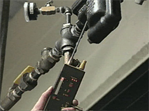 Steam Traps... A proven contributor to energy loss are steam leaks, specifically from faulty steam traps. Steam traps can fail for a variety of reasons causing steam to escape. Since the system is closed it is not possible to know if the trap is operating correctly without the proper tools. By using an ultrasonic detector, maintenance personnel can easily determine if a trap is cycling correctly or if it is letting steam blow by. Testing steam traps using ultrasound requires very little training, however a basic understanding of how a particular steam trap operates is certainly helpful. Is the trap blowing steam? Listening for the tell-tale rushing sound of a leak enables the user to make an accurate judgement immediately. If done regularly, this simple test can save tens of thousands of dollars in energy costs.
Misconception - Ultrasonic instruments are too costly for what you get.
Comparatively speaking, ultrasonic detectors are actually one of the least expensive PM technologies available, yet they remain quite versatile. Locating and repairing leaks in air, vacuum, or specialty gas systems, as well as faulty steam traps quickly cost justifies the use of ultrasonics. New digital detectors, recently introduced, are much more compact, offer greatly improved accuracy and sound quality, making ultrasonics a valuable addition to predictive/preventive maintenance programs.
*Dynamic Noise Discrimination (DND) is a trademark of the Superior Signal Company LLC